
|
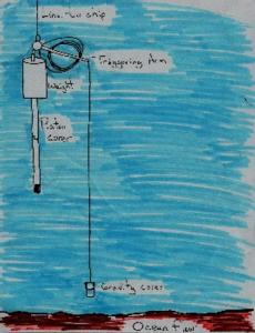
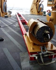
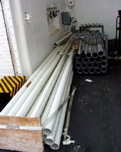
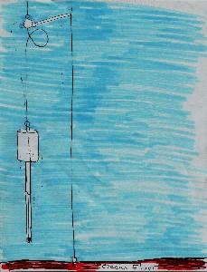
19 June, 2000Coring Equipment and How it all Works As we head towards ice on this Monday, I have been researching the equipment needed to take core samples. Hopefully in the next day or two, we will be testing the coring equipment in ice conditions. We will attempt to extract a 30-meter core sample. It's time for mud, and lots of it! The coring mechanism is made up of many parts, both big and small. As you read through the descriptions, take a look at the pictures and illustrations to help you form an image of just what a coring assembly looks like and how it operates. Core Cutter This is the lowest part of the core assembly. It has sharp edges which cut and shape the sediment entering the core liner as the corer goes into the sediment. Core Catcher This piece rests on the upper edge of the core cutter. Curved finger-like projections extend down to the lowest part of the core liner. The core catcher helps keep the sediment in the core liner when the coring system is being brought back to the ship. Core Liner The core liner is composed of 4'" PVC pipe. PVC pipe is recommended because is readily available, stronger that other liners, and can easily be split lengthwise in the field. The core liner fits inside the metal core barrels and is where the sediment will be contained. Core Barrels The core barrels are 10 foot metal tubing that weight approximately 165 pounds each. The barrels are connected together by couplings that slide over the tubing and are held in place with screws. Piston This is attached to the lowest part of the core barrel assembly. It passes through the entire length of the core as the whole mechanism goes into the sediment. In other words, it stays on the surface of the ocean floor as the coring barrels and coring liner passes into the sediment. Piston Stop This four-inch piece of equipment prevents the piston from traveling through the center of the center tube of the corehead. Corehead For a 30-meter core, a 5000-pound head is recommended. For a 15-20 meter core, a 4000-pound head is recommended. Trigger Arm The trigger arm holds the corehead in place. When the trigger arm "opens" the piston core is dropped at a freefall. Gravity Corer Activates the trigger arm. Illustration 1 The piston corer is lowered from the side of the ship by a 5/16" wire. Below the piston corer is a small gravity corer. Illustration 2 As the gravity corer touches the ocean floor, the triggering arm is activated. This sends the piston corer falling in a freefall to the ocean floor. Illustration 3 When the piston corer goes into the sediment, the piston inside stops at the surface. The piston corer continues down. The piston inside creates a pressure difference between the top and the bottom of the piston corer. This allows the sediment to enter the core liner without any deformation.
Contact the TEA in the field at . If you cannot connect through your browser, copy the TEA's e-mail address in the "To:" line of your favorite e-mail package. |